![]()

|
FireDot.com |
![]()
CHAPTER III
SYSTEM DESIGN
This section will cover the proper design of the Pyro-Chem Kitchen Knight ii Restaurant Fire Suppression System. It is divided into three (3) sections:
- Nozzle Coverage and Placement.
- Piping Limitations.
- Detector Requirements.
Each of these sections must be completed before attempting any installation.
NOZZLE COVERAGE AND PLACEMENT
This section will provide guidelines for determining nozzle type, positioning and quantity for duct, plenum and appliance protection.
A. DUCT PROTECTION
It is not required that the fan be shut down or the exhaust duct be dampered for the system to operate properly. Each nozzle is approved to protect exhaust ducts of unlimited length.
Duct protection requires that a nozzle by positioned to discharge up, into the duct. The nozzle is a Model 2D, Part No. 551038.
The Model 2D duct nozzle is a two (2) flow nozzle. A single 2D nozzle is capable of protecting square or rectangular duct with a maximum of 100 in. (254 cm) perimeter, with the longest side being a maximum of 34 in. (86.4 cm). It can also provide a round duct with a maximum diameter of 31 7/8 in. (81 cm).
Two (2) Model 2D duct nozzle can protect a square or rectangular duct with a maximum of 150 in. (381 cm.) perimeter, with the longest side being a maximum of 51 in. (129.5 cm). They can also protect a round duct with a maximum diameter of 47 1/2 in. (120.7 cm).
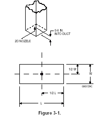
When two (2) 2D duct nozzles are used to protect a single duct, the cross sectional area of the duct must be divided into two equal symmetrical areas. The nozzle must then be installed on the centerline of the area it protects and aimed directly into the duct opening.
The nozzle(s) must be installed on the centerline of the duct, with the tip located 0 to 6 in. (15.2 cm.) into the opening , and aimed directly into the duct opening. See Figure 3-1.

Transitional Ducts - The protection of non-standard ducts should be reviewed by the authority having jurisdiction. Pyro-Chem Kitchen Knight II recommends that transition ducts be protected as follows:
a. Transition ducts - larger or smaller
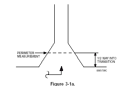
In cases where the duct/plenum interface opening is larger then the final exhaust duct, measure the perimeter/diameter of the duct halfway between the largest and smallest section (or the average perimeter/diameter). The nozzle is to be located within 0-6 in. (15.2 cm) of the duct /plenum interface (not at the point where the measurement was taken), centered under the final exhaust duct opening. See Figure 3-1a.

b. Transition ducts - larger or smaller
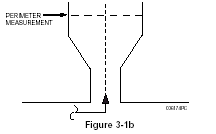
In cases where the duct/plenum interface opening is larger then the final exhaust duct, measure the perimeter/diameter of the final exhaust duct. The nozzle(s) is to be located within 0-6 in. (15.2 cm) of the duct /plenum interface, centered in the opening. See Figure 3-1b.

b. Multiple Risers
In case of multiple risers, each riser is protected as an individual duct. See Figure 3-1c.

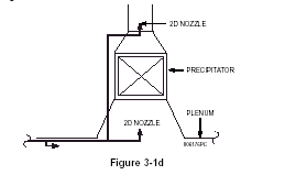
Electrostatic Precipitator - Ducts utilizing electrostatic precipitator must be protected above and below the unit. Standard duct nozzles are used in this application. See Figure 3-1d.
