![]()

|
FireDot.com |
![]()
FUSIBLE LINK DETECTOR INSTALLATION
Fusible links are always used in conjunction with the Model MCH3 Mechanical Control Head. After mounting the cylinder and control head, the fusible link line can be installed. The first step to installing the fusible link line is to install the detector bracket(s). These brackets must be installed in the plenum area of the ventilation hood over all protected appliances and in each duct. See Chapter III for detector placement guidelines.
Note: Only ML-style Fusible Links can be used.
Connect the fusible link brackets together using 1/2" conduit and the conduit connectors supplied in the detector kit (Model FLK-1). A Pyro-Chem Kitchen Knight II corner pulley must be used whenever a change in conduit direction is necessary. the conduit is connected to the control head through a knockout in the upper left-side corner.
In general. fusible links centered in the detector brackets are connected in series using 1/16 in. (.2 cm) diameter stainless steel cable. The spring plate in the control head maintains tension on this series of fusible links. If the tension is released for any reason (i.e. a fusible link separates), the control head will operate and actuate the system. Maximum limitations for the fusible link detection line are as follows:
Fusible links can be installed with or without fusible link Model EN-MCU3, MCH3, and NMCH3 Control Heads and CBP-1, SBP-1, and WBP-1 Pulley Elbows
Maximum # of detectors: 20
Maximum Length of cable: 150 ft. (45.7 m)
Maximum # of
pulleys:
40
1. Fusible Link Installation Without Hangers.
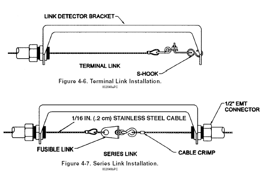
Begin installing links at the terminal bracket. The link is connected to the far side of the terminal bracket using an "S" hook. The "S" hook must be crimped closed after the link is installed. A tight loop is then made in the cable and secured by the crimp provided. This loop is connected to the other side of the terminal link (see Figure 4-6) and the cable fed through the conduit to the next bracket. The cable proceeding from the terminal link will be used to connect the series links (see Figure 4-7). Series links must be centered in their detector brackets.
After the last link in the series is connected, the cable should be fed through the conduit back to the control head. Thread the cable through the hole in the fusible link ratchet wheel. The line must then be crimped, and the crimp positioned inside the center of the ratchet wheel.
 .
.