![]()

|
FireDot.com |
![]()
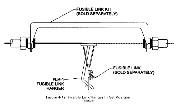
Check to ensure that the fusible link hanger(s) remain centered in the bracket after the fusible link line is set. See Figure 4-12.
NOTE: If wire rope require slicing, a splice is to be a minimum of 12 in. (31 cm) from any pulley elbow or conduit adaptor to avoid interference.
THERMAL DETECTOR INSTALLATION
Thermal detectors are always used in conjunction with the Model ECH3 Electrical Control Head. After mounting the cylinder and control head, the thermal detector(s) can be installed. Install the thermal detector(s) in the plenum area of the ventilation hood over all protected appliances and in each duct. See Chapter III for detector placement guidelines. Follow the instructions included with the detector for proper detector mounting procedures.

SETTING THE CONTROL HEAD
1. Model MCH3/NMCH3 Mechanical Control Head.
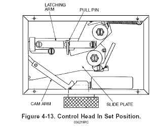
Once the fusible link is set, he control head can be placed in the set position. To set the control head, the slide plate is moved from right to left, ensuring the bolt extending from the cam arm is in the slot provided in the slide plate. Continue moving the slide plate to the left until the latching arm is in the locked position. Insert the pull pin into the hole in the slide plate above the latching arm. This will lock the control head in the set position, eliminating accidental actuation during the rest of the installation procedure. See Figure 4-13.
