![]()

|
FireDot.com |
![]()
2 Electrical Gas Shut-Off Valve Installation
The Model MCH3/ECH3/NMCH3 Control Head is used to operate the electrical gas shut-off valve. This valve is located in the fuel gas supply line to the cooking appliance(s). The valve body has an arrow which indicates direction of gas flow through the valve. A reset relay must always be used with an electrical gas shut-off valve. For proper wiring of the electrical gas shut-off valve, see Figure 4-15.
TEE PULLEY INSTALLATION
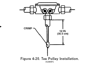
The Model TP-1 Tee Pulley is used to connect two (2) mechanical gas valve or two (2) remote mechanical pull stations to a single control head. The cable proceeding from the control head must always enter the branch of the tee pulley. See Figure 4-20.
A tee pulley that is used to close two (2) gas valves can only be used to close gas valves with similar stem travel. Gas valves from 3/4" (1.9 cm) up to 1 1/2" (3.8 cm) can be used on the same tee pulley. A 2" gas valve can be used only with another 2" gas valve. Gas valves from 2 1/2" up to 3" can be used on the same tee pulley. As an example, using a 3/4" gas valve with a 3" gas valve will not allow the 3" valve to fully open.
CAUTION: The tee pulley must never be used to connect multiple fusible links lines to a single control head.

MINIATURE SWITCH INSTALLATION
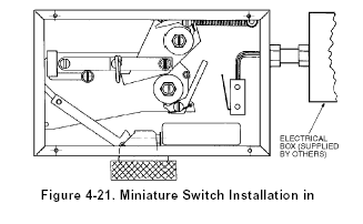
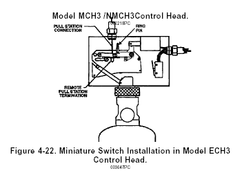
The Model MS-SPDT, MS-DPDT, MS-3PDT, or MS-4PDT Miniature Switch is available for use where an electrical output is required. These switches can be field installed in the control head. See Figure 4-21 and Figure 4-22 and refer to Instruction Sheet, Part No. 551159, included with switch shipping assembly, for detailed mounting instructions.


NOTE: The Model ECH3 Control Head is supplied with a Model MS-DPDT Miniature Switch. However, one set of contacts on the switch must be used in the actuation/detection circuit and cannot be used for electrical output.
NOTE: No electrical connections shall be made inside the control head. All electrical wiring shall exit the control head through the knock-out on the side of the box. All electrical connections must be made in an approved electrical box.
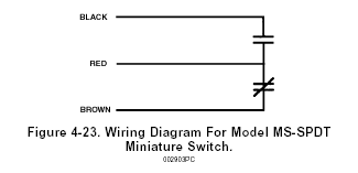
These switches may be used to provide an electrical signal to the main breaker and/or operate electrical accessories provided the rating of the switch is not exceeded. Wiring connections are shown in Figure 4-23. The contact ratings for the switch is as follows:
Contact Ratings For Miniature Switches
21 amps 1 HP, 125, 250, 277 VAC or 2 HP, 250, 277 VAC
