![]()

|
FireDot.com |
![]()
| General Piping Requirements |
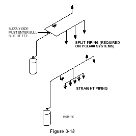
| 1. Split piping and straight piping are both allowed on a PCL-300 and PCL-460 system. |
| 2. PCL-600 systems must use split piping only, with no nozzle located before the split, and with a maximum of 14 flow points per side. 1.2 in. minimum piping must be used up to the first split. |
| 3. Maximum volume for 1/4 in. pipe between a nozzle and the preceding tee is 410 mls. |
| 4. Maximum flow numbers for 1/4 in. pipe is 6. |
| 5. Maximum number of elbows between a nozzle and the preceding tee is 5. |
| 6. Maximum of 25 elbows are allowed in the total piping system. |
| 7. Maximum difference in elevation between the tank outlet and any nozzle, or the tank outlet and the highest and lowest horizontal pipe run, is 10 ft. (3.1 m). |
| 8. No traps are allowed in the piping network. |
| 9. Pipe lengths are measured from center to center of fittings. |
| 10. The internal equivalent length volume of fittings does not have to be considered as part of the total pipe volume. |
| 11. When utilizing different size pipe in the system, the largest size must start first and the additional pipe must decrease as it approaches the nozzle. |
| 12. Elbow(s) or swivel adaptors located at the nozzles do not have to be counted in the 25 elbow maximum requirement. |
| 13. Reducing bushings are allowed when reducing to a smaller pipe size. |
14. Additional piping
requirements when protecting a range, work, or a fryer:
|

Design Steps
| Step No. 1 | Determine number of flow points required based on duct size, plenum size and type, and size of all appliances. |
| Step No. 2 | Determine size and quantity of tanks required. Refer to the chart in "General Piping Requirements" to determine the maximum amount of flow numbers allowed per each tank size. |
| Step No. 3 | Layout nozzles, piping diagram, and tank location. Determine pipe lengths as accurate as possible. Make certain maximum number of elbows is not exceeded. Note: Tanks cannot be manifold together. Each tank must have a separate piping network. |
| Step No. 4 | Add all the lengths of each pipe run and multiply by the mls./ft. listed in the Volume Chart. If the sum falls with in the acceptable range noted in general Piping Requirements, that pipe size is acceptable. If the calculated volume is too large, recalculate the volume using the ml per foot of a smaller pipe size Prize sizes can be mixed but Rule No 11 of the General Piping Requirements must be followed. |
| Step No. 5 | Check to make certain minimum volumes, maximum volumes and maximum volumes allowed between first nozzle and last nozzle is not exceeded (Tank Chart). Check each rule in "General Piping Requirements" to make certain that none have been exceeded. If any requirement is exceeded, change to a different pipe size and recalculate. |