![]()

|
FireDot.com |
![]()
ENCLOSURE INSTALLATION
INSTRUCTIONS
MODEL EN-MCU3 (P/N551208)
AND
MODEL EN-S (P/N 550966)
MOUNTING
The Model EN-MCU3 and/or EN-S Enclosure must be securely anchored to the wall using bolts or lag screws. The wall to which the enclosure is attached must be sufficiently strong. The enclosure should never be fastened to dry wall or similar material. If this type of wall is encountered, studs must be located and the enclosure fastened to them.
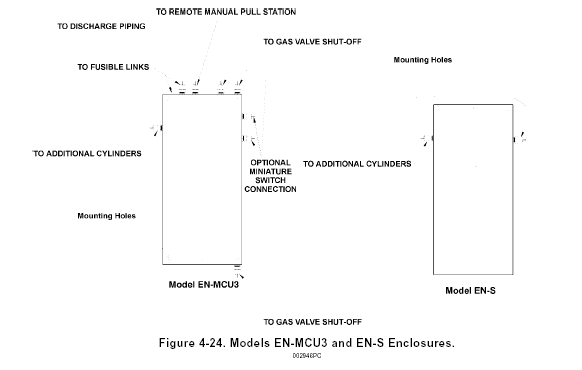
Three (3) center mounting holes allow either enclosure to be mounted on a single stud. Four (4) corner mounting holes are also available. See Figure 4-24.

FUSIBLE LINK DETECTOR INSTALLATION
The Model EN-MCU-3 Enclosure can support a fusible link detection system. The Model EN-S Enclosure cannot support a fusible link detection system and must be used in conjunction with the Model EN-MCU3 Enclosure or a Model MCH3/ECH3/NMCH3 Control Head.
After mounting the enclosure, the fusible link line can be installed. The first step to installing the fusible link line is to install the detector brackets. These brackets must be installed in the plenum area of the ventilation hood over all protected appliances and in each duct. See Chapter III for detector placement guidelines. Connect the fusible link brackets together using 1/2 in. (1.27 cm) EMT conduit and the conduit connectors supplied in the detector kit (Model FLK-1/1A). Pyro-Chem Kitchen Knight II corner pulleys must be used whenever a change in conduit direction is necessary. The conduit is connected to the enclosure through a top knockout.
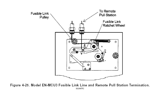
See Fusible Link Detector Installation Section of this Chapter for fusible link installation guidelines. Before attaching the stainless steel cable to the fusible link line ratchet wheel, it must be run below the fusible link line pulley in the enclosure. See Figure 4-25.
