![]()

|
FireDot.com |
![]()
SETTING THE MODEL EN-MCU3
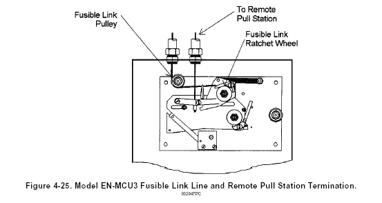
After the last link in the series is connected, the cable should be fed through the conduit back to the Model EN-MCU3. It must be fed under the fusible link line pulley and through the hole in the fusible link ratchet wheel. The line must then be crimped, and the crimp positioned inside the ratchet wheel.
NOTE: Crimps always be used in conjunction with two (2) cable lengths. Loops are the accepted method of connecting the cable to mechanical components. The crimp must never be used on a single cable.
Crimps must always be used in conjunction of two (2) cable lengths. loops are the accepted method of connecting the cable to mechanical components. The crimp must never be used on a single cable.
The fusible link line can now be put into a set position by tensioning the fusible link line. This is accomplished by using a 1/2" hex wrench on the fusible link line ratchet wheel. The ratchet wheel will be ratcheted in a clockwise direction until the spring plate is parallel to the top of the enclosure. Te fusible link line is now in a set position.
Once the fusible link line is set, the model EN-MCU3 Enclosure can be placed in the set position. To set the Model EN-MCU3, the slide plate is moved from right to left, ensuring the bolt extending from the cam arm is in the slot provided in the slide plate. Continue moving the slide plate to the left until the latching arm is in the locked position. Insert the pull pin into the hole in the slide plate above the latching arm. This will lock the control mechanism in the set position, eliminating accidental actuation during the rest of the installation procedure. See Figure 4-25.
REMOTE PULL STATION INSTALLATION
The Model RPS-M Remote Mechanical Pull Station is used for remote manual actuation of the Model EN-MCU3 it is to be located near an exit in the path of egress from the hazard area no more than five feet above the floor.
The Pull Station is connected to the Model EN-MCU3 using 1/16 in. (.2 cm) diameter stainless steel cable. The cable enters the Model EN-MCU3 through a knockout in the top of the enclosure. See Figure $-25.
See Remote Pull station Installation Section of this chapter for remote pull station installation guidelines.