![]()

|
FireDot.com |
![]()
GAS SHUT-OFF VALVE INSTALLATION
The Model EN-MCU3 can be used to operate a mechanical gas shut-off valve. This valve is located in the fuel gas supply line to the cooking appliance(s). The valve body has an arrow which indicates direction of gas flow through the valve. The gas shut-off valve is spring loaded and requires five pounds of force to hold it open. This force is supplies by a 1/16 in. (.2 cm) diameter stainless steel cable that is connected to the Model EN-MCU3.
See "Gas Shut-Off Valve Installation" section of this chapter for gas valve shut-off installation guidelines.
After the valve is installed in the gal line, 1/2 in. (1.27 cm) conduit must be run from top center knockout of the gas valve box to the top or bottom knockout in the enclosure. See Figure 4-24. A Pyro-Chem Kitchen Knight II corner pulley is used wherever a change in conduit direction is required.
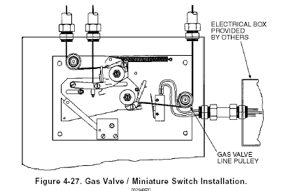
Remove the gas valve cover and thread the stainless steel cable through the conduit back to the Model EN-MCU3. If the cable enters the enclosure through the bottom knockout, the cable must run over the gas valve line pulley (see Figure 4-26). If the cable enters the enclosure through the top knockout, the cable must be run under the gas valve line pulley (see Figure 4-27). Thread the cable through the hole in the gas valve ratchet wheel. The line must then be crimped, and the crimp positioned inside the center of the ratchet wheel.
CAUTION: The gas valve must always utilize the gas valve pulley and exit the top or bottom of the enclosure. The gas valve cannot exit the side of the enclosure.
At the gas valve, loop the cable through the valve stem and secure it with the crimp provided (see Figure 4-18).
The gas valve line can now be put into a set position by applying tension to the gas valve line. This is accomplished by using a 1/2 in. (1.27 cm) hex wrench on the gas valve ratchet wheel. The ratchet wheel will be ratcheted in a clockwise direction until the gas valve is fully open. Secure gas valve cover plate to the gas calve box with the four (4) screws provided. The gas valve lone is now in a set position. See Figure 4-26 and/or Figure 4-27.
CAUTION: Do not over tighten gas valve. Over tightening the gas valve may cause the valve to not close completely, thus not fully shutting the fuel supply off to the appliance.
![]()
MINIATURE SWITCH INSTALLATION
The model MS-SPDT, MS-DPDT, MS-3PDT, or MS-4DPT-EN Miniature Switch is available for use where an electrical output is required. These switched can be field installed in the Model EN-MCU3. See Figure 4-26 and/or 4-27.
These Switched may be used to provide an electrical signal to the main breaker and/or operate electrical accessories provided the rating of the switch is not exceeded. Wiring connections for the Model MS-SPDT are shown in Figure 4-23. The contact ratings for both switches are as follows:
Contact Ratings For Miniature Switches: 21 amps 1 HP, 125,250,277 VAC or 2 HP, 250, 277 VAC
Three (3) knockouts are provided for Miniature Switch wiring. The upper right-side knockout must be used when the gas valve line exits the bottom of the enclosure (see Figure 4-26). The lower right-side knockout must be used when the gas valve line exits the top of the enclosure (see Figure 4-27). An additional knockout located on the top of the enclosure is also provided (see Figure 4-24) and may be used in either situation.
NOTE: No electrical connections shall be made inside the control head. All electrical wiring shall exit the control head through the knock-out on the side of the box. All electrical Connections must be made in an approved electrical box.